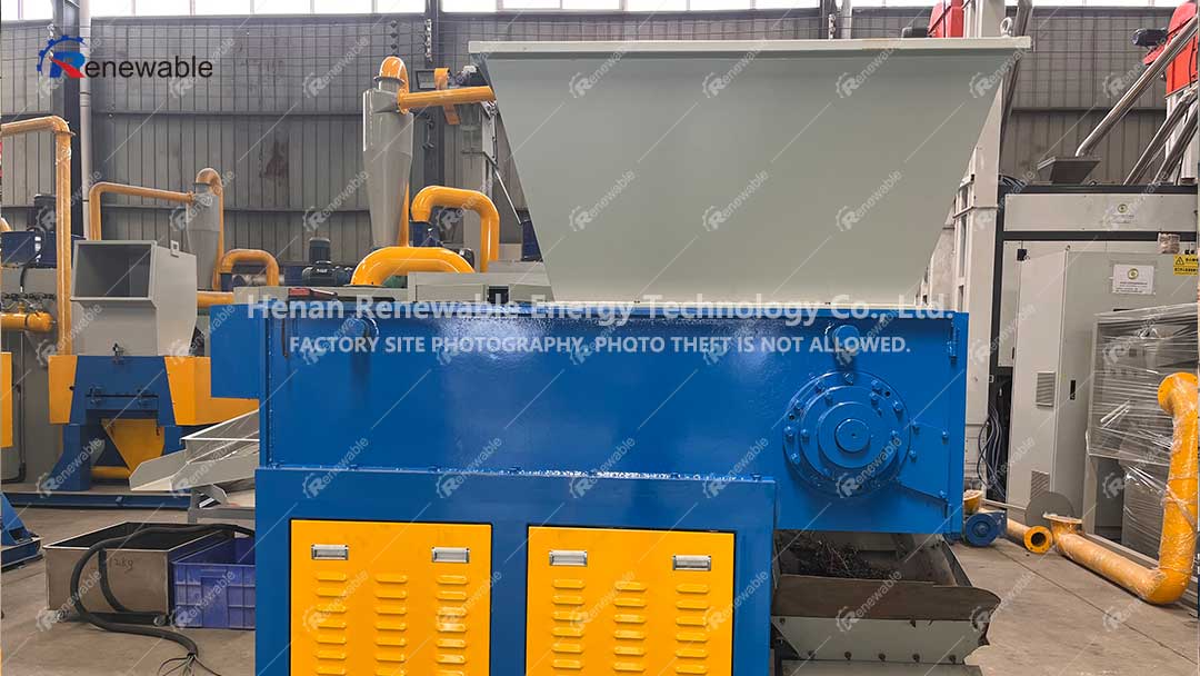
Core components of single-shaft shredder
The structural design of a single-shaft shredder is centered around achieving efficient crushing and stable operation, primarily comprising the following key systems
1. Power System: Comprised by a high-performance motor and gear reducer, it delivers low-speed (typically 50-150 RPM) and high-torque output, ensuring crushing capability for high-toughness materials.
2. Crushing System: It consists of a rotor shaft (equipped with rotatable blades, typically made of SKD11 or Cr12MoV steel), fixed blades, and a screen. The blades are arranged in a “V” shape or feature a detachable insert design, achieving a minimum shear clearance of 0.1mm. This setup, combined with the screen, controls the output particle size (minimum 20mm).
3. Feeding and Pushing System: A hydraulic pushing cylinder drives a pushing plate to force-feed materials, ensuring continuous contact between the materials and the rotor shaft, thereby enhancing crushing efficiency.
4. Control System: Most are equipped with a PLC programming system, enabling automatic reversal (for overload protection), current monitoring, and remote operation. Some models are also fitted with a rotor shaft cooling system to prevent the burning of low-melting-point materials.
Single shaft shredder working process
1.Material Feeding: The materials enter the crushing chamber through the hopper and are pushed towards the high-speed rotating rotor shaft by a hydraulic pusher.
2. Crushing Process: The moving blades on the knife shaft and the stationary blades generate a shearing force, which tears and cuts the materials. Materials that do not meet the required particle size are recirculated within the chamber for further crushing until they pass through the screen and are discharged.
3. Safety Protection: The equipment is equipped with bearing seals (waterproof and dustproof), an overload automatic shutdown feature, and emergency stop buttons to ensure operational safety.